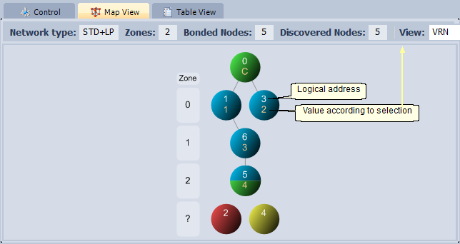
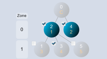
The graphical representation of IQMESH network. It is not a complete network topology but just an illustration of paths of discovering individual Nodes during the Discovery process. The map can be read out from the Coordinator by the Update Data button on the control panel.
•Function of colors:
oGreen - Coordinator
oBlue - Discovered Node
This Node has been discovered, has a VRN assigned and may take a part in routing.
oYellow - Undiscovered but accessible Node
This Node has not been discovered, but has answered to test packet during the Poll Nodes process.
oRed - Inaccessible Node
This Node has not answered to test packet during the Poll Nodes process.
oBlue/green - Discovered Node/Coordinator (the enumeration must be performed first to be displayed)
This Node in the main network is also a Coordinator of a nested network. If the enumeration was not performed the Node is displayed in blue.
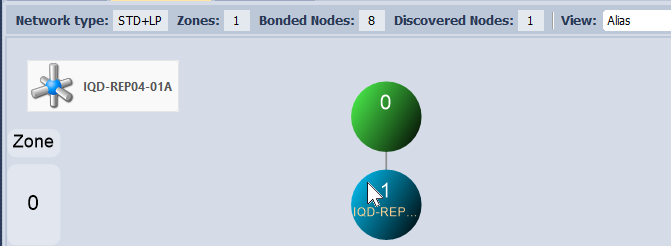
•Hover over the network device to see the device alias.
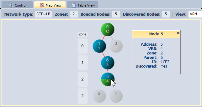
•By doubleclick to a network device (Node) the path from the Coordinator to this Node on the map is highlighted and table with detailed information is displayed. Return to normal view can be accomplished by doubleclick to an empty area in the map.
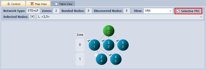
•Check the Selective FRC checkbox to display checkboxes on Nodes in the map. These checkboxes are used for a Node selection of the Selective FRC. The selection is applied only for FRC sent using the Perform Selected Operations button and the Maintenance tab.
oUse the right mouse button click on the space outside the map picture to open menu:
▪Select All
▪Unselect All
oIt is also possible to do group selection. The group can be created by:
▪Shift key + dragging the mouse across multiple Nodes
▪Ctrl key + click on a Node
Unselected Nodes and Coordinator are displayed in gray color.
Click the checkbox of selected Node to change state of all checkboxes in the group.
Return to normal view can be accomplished by doubleclick to an empty area in the map.
•Click the right mouse button to the network device to open the menu (menu items may differ according to the IQRF OS and DPA version detected).
oSend Packet from DPA Test Terminal
Sends the packet currently selected in the DPA Test / Data to send window to the given network device. The addressee is set automatically:
▪In case of main network only NADR is set automatically.
▪In case of nested network following values are automatically set:
❑ NADR according to the Coordinator Address on the control panel.
❑ PNUM to COORDINATOR peripheral.
❑ PCMD to BRIDGE command.
❑ subNADR of the BRIDGE command according to the selected network device in the map.
oIndicate
Sends the Indicate command to the given Node.
oLED Red Pulse
Sends the LED Red Pulse command to the given network device.
oLED Red On
Sends the LED Red On command to the given network device.
oLED Red Off
Sends the LED Red Off command to the given network device.
oOS Read
Sends the OS Read command to the given network device. The result is displayed in the Table View.
oUnbond Node
Unbonds given Node on both sides (Coordinator and Node).
oUnbond Node only in Coordinator
Unbonds given Node in the Coordinator only.
oRemove Node Address
Assigns a temporary address 0xFE to the Node. The Node stays in the IQMESH network (it is not unbonded but prebonded).
oEnable Prebondig
Enables prebonding of new Nodes to the given network device. This item is available only if Remote Bonding on Control tab is active.
oDisable Prebonding
Disables prebonding of new Nodes to the given network device. This item is available only if Remote Bonding on Control tab is active.
oClear flag: Prebonding provided
Clears information about prebonded Node in memory of given network device. This item is available only if Remote Bonding on Control tab is active.
oSwitch to Nested Network (visible for Coordinator/Node device only)
Updates data from given network device and creates map and table of the nested network.
oSwitch to Main Network (visible for Coordinator/Node device only)
Updates data from Coordinator of main network and creates map and table of the main network.
Reads TR configuration from given network device and opens the TR Configuration window. The configuration can be changed and uploaded back to given network device.
oReset TR
Sends the Reset command to the given network device.
Sends the Restart command to the given network device. This command is similar to the Reset command except RFPGM on reset (when it is enabled) is always skipped. For more information see document IQRF DPA Framework Technical guide.
oEnumerate (full)
Reads OS info, TR configuration and list of supported peripherals from given network device. The Table View window is automatically displayed after data reading.
▪Edit F2
Allows to edit alias.
▪Delete
Deletes the alias.
▪Insert Product Name
Inserts the product name from the IQRF Repository. The item is enabled only if the device was enumerated and the product name was found in the IQRF Repository according to its HWPID.
▪Insert Product Name to all Devices
Inserts the product name from the IQRF Repository to the Coordinator and all Nodes.
oRead Actions
Downloads Action rules to the Action table.
oClear Actions
Clears all Action rules in the given Node.
oCopy MID
Copies MID to the Windows clipboard. The item is enabled only if an enumeration was read from given network device.
oShow IQRF Alliance Product Info
Shows the product information from the IQRF Repository.This item is enabled only if the given device is enumerated and the IQRF Repository knows its HWPID.
•Use the Export button on control panel to export the map to BMP, PNG, TIF, JPG, GIF, EMF or XML file. The XML file contains map data only (without enumeration data).
•Use the Import button on control panel to import the map from defined XML file. This feature is usable even for non DPA applications.
•The map can be zoomed in / zoomed out by the mouse wheel.
•Click the mouse wheel to fit map.
•If the map is zoomed beyond the borders of the window, it is possible to drag the map by the left mouse button.
•Hot keys for working with map:
oCtrl+Alt+U ... update data from Coordinator and create map and table
oCtrl+plus ... zoom in
oCtrl+minus ... zoom out
oCtrl+0 ... fit map
oArrows ... fine map shifting
oShift+arrows ... coarser map shifting
oPage Up, Page Down ... coarse map shifting
oHome ... jump to the top of map
oEnd ... jump to the bottom of map