

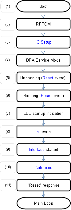
 When device (1) boots it first
optionally goes into (2) RFPGM mode supposed this mode is (enabled)
configured on the OS tab of the TR Configuration dialog box at IQRF IDE. RFPGM
mode is indicated by a repeated long green LED light followed by short red LED
flash. RFPGM mode is terminated depending on its configuration. RFPGM mode is
fully controlled by IQRF OS.
When device (1) boots it first
optionally goes into (2) RFPGM mode supposed this mode is (enabled)
configured on the OS tab of the TR Configuration dialog box at IQRF IDE. RFPGM
mode is indicated by a repeated long green LED light followed by short red LED
flash. RFPGM mode is terminated depending on its configuration. RFPGM mode is
fully controlled by IQRF OS.
Next (3) IO Setup is executed if one is enabled.
At the very beginning, it is possible to remotely connect to the device at so-called (4) DPA Service Mode (DSM). A special tool e.g. CATS - DPA Service Tool from IQRF IDE is needed to do it. In the DPA Service Mode, the device can be fully controlled by individual DPA commands regardless of the device configuration so it gives the possibility to update or fix a corrupted device configuration, find out its network address, (un)bond it, find out OS information, reprogram the device etc. DSMactivated API variable indicates whether DSM was started during device startup. Upon DSM exit, the device is always reset. The device first tries to establish DSM session at the fixed channel number 0[*] and then it tries an alternative channel optionally specified at TR Configuration. CATS - DPA Service Tool must be set to use the same required channel for the DSM session.
[*] Due to local government regulation, devices operated in Israel are distributed with limitation for 916 MHz band and channels from 133 to 140 only. Therefore fixed DSM channel is set to 133. Furthermore, DCTR-77Dx devices are technically limited by SAW filter for 868 MHz band and channels from 45 to 67, therefore fixed DSM channel is set to 45.
Brown-out Reset is disabled now and user interrupt is enabled so Interrupt event can be raised if any interrupt source is enabled from now on.
Bonding or unbonding phase being valid only for [N] devices comes next.
By default, the bonding or the bond removal (unbonding) at [N] side is initiated and controlled by a “default“ IQRF button connected between ground and PORTB.4 MCU pin which is normally available at IQRF development tools. The default behavior can be modified by the implementation of Reset event that is raised during bonding and/or unbonding phases. To keep default behavior but with a custom bonding button, an event BondingButton can be used.
Already bonded [N] can be (5) unbonded by the following procedure. Switch off the [N]. Keep pressing the button and switch on the [N]. Skip optional RFPGM mode depending on its configuration (typically pressed button terminates it). Keep the button pressed. Green LED is then on. After 2 seconds the green LED goes off. Release the button immediately within 0.5 s. Unbonding is then confirmed by red LED being on for 1 second and consequently by the rapid red flashes described above. Such complicated unbonding procedure is needed in order to prevent unwanted unbonding caused by accidental button press after the device is reset.
(6) If the [N] is not bonded then its red LED rapidly flashes. [N] waits for the button press. When the button is not pressed while the red LED rapidly flashes the [N] is ready to be bonded using the Smart Connect process. For details please see IQRF OS User's Guide. By pressing the button a bonding process is initiated. If the button is pressed the [N] continuously requests bonding (indicated by a slower red LED flashing) using bondRequestAdvanced IQRF OS function. If the red LED becomes off and a green LED is lit for 0.5 s then the [N] is bonded. If the LP [N] bonds to the STD network, then the [N] unbonds itself immediately and indicates it by red LED for 1 s. If the red LED keeps flashing rapidly after the button is released then the [N] is not bonded yet and the whole bonding phase repeats. If the button is not pressed (while the device operates at LP-RX mode) within approximately 5 hours then the [N] goes into power saving deep sleep mode and red LED stops flashing. From the deep sleep mode, the [N] can be woken up by the button press. Please note that the [N] does not have to be configured for a working network RF channel as the channel is automatically inherited from the network member that provided the bonding and then written to the configuration.
At this point, [N] device is bonded and ready to work on the network. This is indicated by a short red LED flash (7). If the device has a temporary network address (0xFE) then the device flashes twice. [C] devices perform one green LED flash instead when they are ready.
After that, Init event (8) is raised and Interface is started (9) (in the case of [N] devices only when enabled at TR Configuration). If the SPI peripheral is enabled in the TR Configuration, then it is started.
Consequently, an Autoexec (10) is executed if one is enabled.
At (11) if the interface is enabled (always at the [C] device) the device (being always slave interface) sends the following asynchronous “Reset” DPA Request equal (except PCMD) Peripheral enumeration response to the interface master. This time the response code is marked by the asynchronous bit STATUS_ASYNC_RESPONSE.
|
NADR |
PNUM |
PCMD |
HWPID |
PData |
|
NADR |
0xFF |
0x3F |
? |
See DPA Request of Peripheral enumeration |
Then the [C] device checks a presence of the connected interface master device during startup. If the data of the “Reset” response are not collected from the interface by the interface master within 100 ms then the device assumes that the interface master is not present. When the interface master is not connected an extra green LED flash is carried out and API variable IFaceMasterNotConnected is set to 1.